
31 KiB
V2 OA / SA semantics research
Research date: 2026-09-05. This is an implementation decision aid, not a claim that the proposed features already exist. It distinguishes Arcadia method, Capella implementation evidence, and recommended Studio behavior.
Evidence and limits
Sources are the official Arcadia reference site and the Eclipse Capella repository. Repository source inspection was pinned to commit 3153b930a4284f6c82952658f1e8d8d6d8c8f340 where indicated; user documentation links below use master and can change. Relevant original screenshots were also extracted from the already-installed Capella 7.0.1 documentation JARs and visually inspected. This researcher did not operate a live Capella session. Native runtime inspection is separate work, and old documentation screenshots must not be presented as screenshots of that runtime.
The Ecore schemas expose inherited or permissive structures that are further constrained by validation rules. For example, SystemComponent structurally has a child-component reference, while the SA validation rules forbid internal decomposition of the System. Schema availability alone is not evidence that a concept is legal in an engineering perspective.
No source code or visual assets were copied into Studio. The recommendations below are an independent synthesis. They do not establish Capella file compatibility, full metamodel conformance, simulation semantics, or support for Logical/Physical Architecture.
Perspective boundaries
OA describes stakeholder work and its operational context. Identify what people, organizations, and other entities must accomplish, their capabilities, activities, interactions, and operational conditions. Avoid assuming the future System of Interest as the solution. SA describes the selected system contribution: its boundary, externally visible services, interactions with operators and external systems, and expected behavior. A single operational activity may require several system and actor functions; different solution alternatives can satisfy the same operational need. Arcadia Q&A
An OA Actor is an undecomposable operational participant, usually human. An SA Actor is external to the System; it can be human or another system. Consequently, OA Entity → SA Actor is normal and does not mean that the stakeholder became a person. Missions express high-level goals; capabilities express abilities that support them. Activities/functions describe work, and interactions/exchanges describe dependencies between that work. Arcadia language
SA has exactly one System, alongside its external actors. It does not contain the System's internal logical components, software/hardware placement, or deployment nodes. Those belong to subsequent architectural perspectives. SA functions can still have deep decomposition: a functional breakdown does not decompose the System structurally. Capella architecture diagrams, component rules DWF_DC_36–38
Three meanings of nested boxes
| Meaning | Semantic operation | OA / SA application | V2 editing contract |
|---|---|---|---|
| Decomposition / containment | Change an element's semantic parent | OA entity within entity; activity within activity; SA function within function; non-human external actor hierarchy where supported | Explicit Move into / Reparent command. One parent, same perspective, compatible types, no cycles. Move subtree as one undoable transaction. |
| Allocation presentation | Show work inside its performer | OA activities inside entities/actors; SA functions inside the System/actors | Explicit Allocate to command. Moving a function visually is insufficient to change its functional parent. Inspector shows both functional parent and performer. |
| Deployment / hosting | Allocate a behavioral implementation onto hosting resources | Physical Architecture, outside this OA/SA scope | Do not expose a generic SA deployment relation or reinterpret every nested box as a hardware node. |
Capella allows direct allocation of leaf functions/activities. A non-leaf function may appear within a performer as a computed summary of its allocated leaves. That appearance is not a second direct allocation. The official allocation guide also distinguishes functions allocated on subcomponents using a dashed presentation and parent functions using italics. V2 can use its own accessible styling, but must preserve the distinction. Allocation guide
Implementation consequence: retain independent references for semantic_parent, allocation, and diagram containment/presentation. Dragging an activity into an entity should propose allocation; dragging it into another activity should propose decomposition. When splitting an allocated leaf, offer an atomic operation that moves its allocation to the new leaves; never silently leave an illegal direct allocation on their parent. This is a Studio design recommendation.
The direct-allocation uniqueness rule counts ComponentFunctionalAllocation relationships. It does not count role-mediated ActivityAllocation relationships. Do not incorrectly outlaw OA role sharing by treating every role membership as a direct performer allocation. Unicity implementation
Prioritized V2 semantics matrix
P0 means foundational work needed before the dependent rows. P1 means the next implementation group for a meaningful OA/SA workbench, not permission to claim complete V2 while omitting it. P2 covers richer variants that require explicit scope disclosure if absent.
| Priority / concept | OA semantics | SA semantics | Concrete V2 minimum and validation |
|---|---|---|---|
| P0 — perspective and identity | Operational analysis root; typed entities, actors, activities, capabilities | System analysis root; exactly one System; external actors, functions, missions, capabilities | Every element/relation has stable identity and perspective. Reject cross-layer containment and same-layer work allocation to another layer. |
| P0 — structural hierarchy | Entities can own subentities; OA actors cannot decompose | No internal System component tree; non-human external actor composition is distinct from the System | Parent picker plus nested diagram and tree. Prevent cycles. Human participants cannot acquire children. OA schema, component rules |
| P0 — work breakdown | Activities have owned activities | System functions have owned functions; functions may be allocated to the System or an Actor | Leaf/non-leaf distinction; create child, reparent, collapse, expand, focus subtree. Preserve independent performer. functional schema, SA schema |
| P0 — direct work allocation | Entity/Actor → leaf Activity | System/Actor → leaf System Function | At most one direct performer; reject wrong perspective and non-leaf direct allocation. Unallocated leaves are an actionable completeness issue while authoring. allocation implementation |
| P0 — exchanges | Directed Interaction between Activities; communication means connect Entities/Actors | Functional Exchange between output/input function ports; Component Exchange between System/Actor boundaries | Typed endpoints, direction, exchange-item references. An exchange is not an allocation or a sequence occurrence. Distinct parallel exchanges retain distinct IDs. functional schema, OA schema |
| P0 — operational/system goals | Operational capabilities involve Entities/Actors and work/processes | Mission exploits Capability; Capability involves System/Actors, functions, chains/scenarios | Typed involvement and mission-capability links; browse from both endpoints. Do not label all of these relationships “realization.” SA schema, interaction schema |
| P0 — traced counterpart workflow | Can select work/participants/goals to realize in SA | Realizing elements retain links to operational sources | Explicit creation, linking, comparison, and update in either direction; stable many-to-many traces; atomic apply/undo. Detailed contract below. |
| P1 — Roles | A coherent activity group can be assigned to one or more Entities/Actors | No direct SA Role equivalent | Separate Entity→Role and Role→Activity relations; show effective assignments. Transition shared roles using contextual function instances or explicit assignment decisions, not multiple direct allocations of one SA function. Role glossary, OA schema |
| P1 — Processes / Functional Chains | Operational Process references activities/interactions along a path | Functional Chain references functions/exchanges along a path | Ordered occurrence records with stable IDs, including repeated use of the same semantic exchange; continuity checks; capability involvement; highlight the path in diagrams. A flat list alone does not implement branching control semantics. Arcadia language, chain rules |
| P1 — Scenarios | Activity and Entity scenario views use operational interactions | Functional, exchange, and interface scenario views use appropriately typed lifelines/messages | Scenario belongs to a capability; explicit lifelines, ordered messages invoking existing exchanges/operations, pre/postconditions, and referenced states. Retain message identity separately from exchange identity. scenario schema, scenario rules |
| P1 — Modes / States | Owned by an operational participant | Owned by the System or an Actor | State-machine owner; regions; state/mode/initial/final kinds; directed transitions, guard, trigger, effect; entry/do/exit work references; availability of activities/functions, processes/chains, and capabilities. No machine execution claim. state schema |
| P1 — Data and Exchange Items | Operational information conveyed by interactions | Typed information at the system boundary and functional exchanges | Exchange Item with ordered named typed elements, direction/multiplicity where supported; reusable primitive/enum/record types; exchange↔item links. Avoid hard-coding software-only request/response data. information schema |
| P1 — Interfaces | Use operational communication means and exchanged information; do not import implementation contracts indiscriminately | System/Actor interfaces group Exchange Items; participants or their ports provide/require interfaces | Interface contains references to exchange items; explicit provided/required direction and port ownership. Functional exchange is not itself an interface. Interface glossary, structural schema |
| P1 — Communication support | Communication Mean can carry operational Interactions | Component Exchange can carry Functional Exchanges | Explicit exchange-allocation relation, compatible performer endpoints, same perspective; boundary exchange and work exchange remain separate records. OA schema, component rules DWF_DC_13/27/29 |
| P1 — conditions and constraints | Stakeholder context, operational assumptions, performance and constraints | Required qualities, boundary constraints and acceptance conditions | Named text constraints with typed targets and units as data where numeric. Treat prose guards/constraints as descriptions unless an evaluator is actually implemented. Arcadia perspective overview |
| P2 — richer behavior | Role context, ALT/PAR/LOOP scenarios, process control nodes | ALT/PAR/LOOP scenarios, chain control nodes, composite/concurrent state regions | Explicit control/operand structures and ordering; same-layer scenario references; reject malformed fragments. No flattened “sequence” advertised as equivalent. diagram tools, scenario rules |
| P2 — capability relations | Include, extend, generalize Operational Capabilities | Include, extend, generalize System Capabilities | Distinguish these relations from decomposition and realization; disallow self-relations and diagnose cycles according to the declared Studio profile. capability rules |
Arcadia describes operational missions, but the inspected Capella OA schema has no matching Mission class; the class exists in SA. If V2 includes an OA Mission, describe it as support for the Arcadia method, with a Studio-defined representation, rather than claiming exact Capella OA metamodel equivalence. Arcadia Q&A, OA schema, SA schema
The MVP's activity→capability “Contribution” and process→capability “Realization” are Studio concepts. For V2, use capability involvement for local work/process links, and reserve cross-perspective realization for traceability, or explicitly document any retained legacy terminology and migration. Capella has dedicated capability involvement records. interaction schema
Transition mappings and their limits
Capella's transition documentation describes separate entry points and dependency handling. It is not a universal clone-all command. Operational Entity can transition to Actor or be realized by the System. Operational Capability can transition to Capability or Mission. Transitioning an entity can also transition its allocated activities/interactions. The exact dependency closure must be shown before applying a Studio transition. Capella transition entry points
| OA source | SA counterpart | Required Studio decision |
|---|---|---|
| Entity / Actor | External Actor, or the existing System | Decide scope deliberately. Several OA participants may contribute to defining one system boundary. Do not create a second System. |
| Activity | One or more System Functions, allocated to System and/or Actors | Select granularity and responsibility. Preserve independent decompositions. |
| Interaction | One or more Functional Exchanges | Resolve realizing source/target functions; create required ports; retain information-item links. No exchange with unmapped endpoints. |
| Communication Mean | Component Exchange | Require mapped participant endpoints and reconcile exchange allocations. |
| Operational Capability | System Capability or Mission | Choose ability versus high-level goal; do not infer solely from the label. |
| Process | Functional Chain | Map occurrence identities and their work/exchanges; preserve repeated occurrences. Branching and split mappings require explicit resolution. |
| Operational Scenario | Suitable SA scenario | Resolve lifeline/operation types, ordering and referenced states; carry a scenario realization link. |
| Modes/States and transitions | Separate SA-owned machine elements | Resolve owner first, then state/transition mappings, then availability/trigger links. Do not point an SA machine at OA-owned states. |
| Exchange Item / datatype | Shared upper-layer information, or transitioned counterpart | Make reuse versus creation visible. Capella permits upper-layer data/item reuse in downstream layers; it does not permit the same cross-layer reuse for states/modes. |
| Role | No automatic same-kind SA counterpart | Use its activity/performer context to produce suitable functions and actors. |
The first five rows follow the documented entry points and inspected OA/SA/functional schemas; scenario/state/item rows are supported by their realization-bearing schemas and transition dependency documentation. This table is a Studio mapping contract proposal, not evidence that one Capella menu implements every row in both directions. transition entry points, functional schema, scenario schema, state schema
Capella's documented transition engine is conservative and iterative: traced targets can be updated; deleting a source does not automatically destroy the target; rerunning can recreate a deleted target. Its merge UI compares the candidate transition result with the existing target. This supports reviewed updates, but it is not evidence of automatic, lossless reverse transformation. Transition concepts
Explicit bidirectional creation and update for Studio
The user request calls for more than browsing. Implement the following in both OA→SA and SA→OA. These are recommended Studio behaviors; the reverse authoring workflow extends the documented Capella transition workflow.
- Create counterpart / Link existing. Start from either a diagram selection, the model tree, inspector, or source selection. Choose counterpart kind, destination parent, and involved performers. Reuse an existing trace when present; show multiple counterparts rather than silently choosing one.
- Keep canonical semantics. The relation always means “SA element realizes OA element,” even when the command starts in SA. Command direction belongs to transition history, not the meaning of the relation.
- Make reverse creation explicit. SA Function can propose an OA Activity; SA Actor can propose an OA Actor/Entity according to its human/context meaning; Capability can propose Operational Capability. An SA System must not automatically create an OA entity representing the solution under study. An SA interface or internal system-only function may have no useful direct OA counterpart. Let the engineer author or select the operational need and record rationale.
- Preview a dependency-complete change set. Show new counterparts, existing matches, hierarchy changes, proposed allocations, exchanges/ports, process/scenario occurrences, reused information, and links that cannot map. Apply only when required endpoint/ownership choices are resolved. No implicit fallback to unrelated same-name elements.
- Separate propagation from editing. Rename/edit either side normally. Mark affected traces “review needed.” An explicit Compare / Update counterpart action offers per-field Keep target, Apply source proposal, or Edit value. Descriptions and names commonly diverge legitimately between needs and system services.
- Detect concurrent semantic changes. Store a last-reviewed semantic snapshot/signature per trace or transition group. Distinguish source-only, target-only, and both-changed cases. Exclude diagram layout from semantic drift. A previous review baseline is needed; comparing names alone is insufficient.
- Preserve identity and local work. Repeated transition/update is idempotent when nothing changed. Selected changes commit as one undoable transaction. Deletion of one side removes/marks the trace appropriately and offers impact review; it never cascades into the other perspective without an explicit separate model deletion.
- Navigate both ways. Each inspector exposes “Realizes” and “Realized by,” shows counterpart kinds and layers, and opens the counterpart diagram/source location. Back/forward navigation preserves context. Display a trace table for coverage and unresolved decisions.
Many-to-many realization must remain possible. A deterministic update algorithm can safely propose changes for a simple one-to-one pair, but cannot decide how to merge multiple operational activities into one function, or split an exchange across several functions, without engineering choices. Recording an intentional divergence is a successful review outcome, not a synchronization failure.
Behavior rules worth implementing early
The following constraints prevent plausible-looking diagrams from contradicting their model:
- Scenarios: message endpoints must match the referenced interaction/exchange and lifeline types; starts precede corresponding finishes; message exchange items must be supported by the invoked exchange/operation; referenced scenarios stay in the same architecture layer. Capella distinguishes OA
INTERACTIONscenarios from SAFUNCTIONAL,DATA_FLOW, andINTERFACEkinds. User-facing names can be clearer. scenario validation - State machines: validate initial-state cardinality and initial transition count; owner-relative entry/do/exit work and triggers; references to available functions; consistent regions. Capella makes mixed Mode/State hierarchies preference-dependent, so Studio must publish its chosen policy rather than call a stricter rule universally required by Arcadia. state validation
- Chains/processes: sequence/control links must refer to the actual involvement records and have consistent direction. Displaying a parent function's computed exchange is not a new semantic exchange. chain validation, computed links
- Capabilities: self-inclusion, self-extension, and self-generalization are errors. Mismatches between involved actors and actual scenario/process participants are coverage diagnostics. capability validation
- Structural versus completeness issues: reject dangling references, wrong kinds/layers, cycles, and invalid uniqueness; keep missing allocation, uncovered capability, incomplete scenario, or absent realization as visible modeling diagnostics when safe. Do not prevent engineers saving legitimate work in progress.
Original UI evidence and adaptation
Four original screenshots were visually inspected from installed org.polarsys.capella.ui.doc_7.0.1.202503211540.jar and org.polarsys.capella.transitions.doc_7.0.1.202503211540.jar. Matching official repository URLs are listed here so the evidence remains reviewable:
| Original evidence | Observed directly | Useful V2 adaptation |
|---|---|---|
| Capella perspective screenshot | Left model hierarchy; central Activity Explorer with OA/SA tabs; properties, information, semantic browser areas | Keep OA/SA discoverable and provide task guidance; selection coordinates all editing views. |
| Semantic browser screenshot | Three columns for referencing/current/referenced elements; explicit realizing and realized functions, parent, exchanges and related diagrams | A focused relationship inspector with both directions, parent, allocation, and direct diagram/source navigation. |
| First transition example | Separate OA/SA model trees; activity breakdown becomes a function breakdown; the target diagram needs representation setup | Never equate model transition with copying a picture. Offer to create/focus the target view after creating semantic elements. |
| Allocated functions screenshot | Functions drawn inside component boxes while exchanging with functions allocated elsewhere | Nested allocation view; independent work hierarchy. This screenshot uses LA and is evidence of presentation only, not permission for SA internal components. |
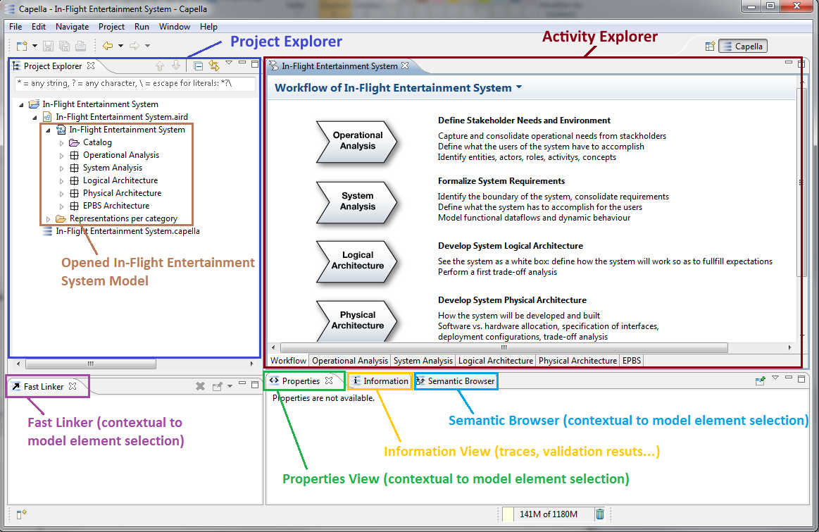
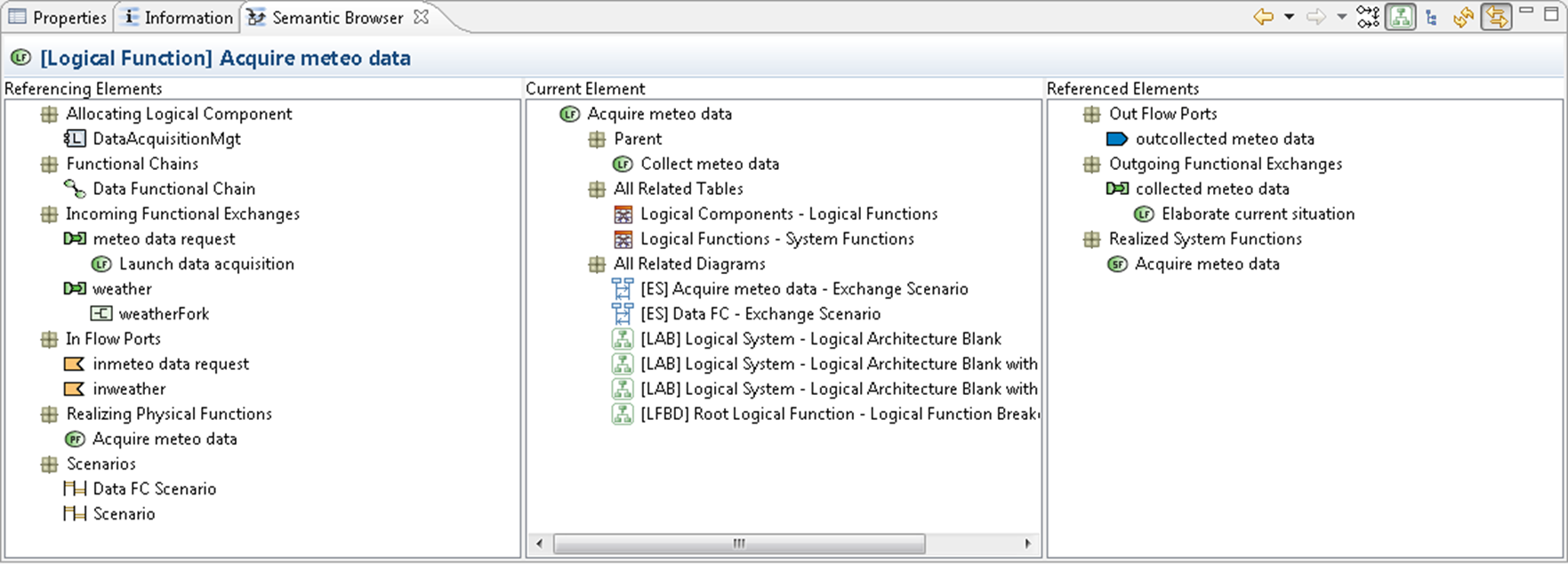
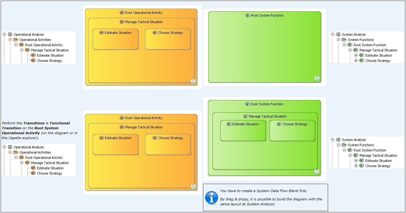
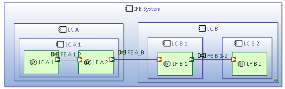
Documentation also confirms the semantic browser has navigation history and can follow selection, and that diagram insert/remove operations can alter graphical presence without deleting semantic elements. V2 should therefore separate Hide from diagram from Delete from model. Semantic browser guide, diagram tools
These images are documentation evidence, not a current-version usability benchmark. No video was played, no timing/accessibility claim was measured, and no claim is made that every depicted command is available unchanged in the installed runtime.
Graphical / textual parity and reviewable completion
Recommended acceptance criterion: every implemented semantic field, reference, hierarchy, scenario occurrence, state-machine relation, interface declaration, and realization decision can be created and edited graphically and textually against one UUID-based model. Graphical diagrams are views, not a second source of truth. If layout/view filtering is persistent, its syntax and persistence belong to the same parity contract.
Useful acceptance examples should cover a general system, such as a rail crossing, rescue service, or industrial water system, with humans, organizations, external systems, physical/information interactions, operating modes, and degraded behavior. Avoid making every function an API call or every item a software message.
The most discriminating end-to-end cases are:
- Decompose OA entities and activities, allocate leaves, show a computed parent summary, and reparent a work subtree without changing its performer.
- Realize one OA activity through both an SA System function and an Actor function; traverse the traces both ways.
- Create an OA counterpart from an existing SA function, retain the SA→OA realization direction, edit both sides independently, and resolve an explicit update without losing either draft.
- Transition a role shared by two participants without creating a multiply allocated SA function.
- Model a process/chain and a scenario with two occurrences of one exchange; save/reopen and undo while preserving occurrence identity and order.
- Link a degraded mode to available work and a guarded transition; show that incorrect owner references are rejected.
- Convey a typed exchange item through a functional exchange and required/provided interface; show valid endpoint and item navigation in diagram, inspector, and source.
- Apply text edits that change containment, allocation, and realization in one transaction; malformed input preserves the prior model. Round-trip both storage forms without dropping newly introduced fields.
Completeness must be reported feature by feature. A new enum value, label, inspector field, or sample diagram is insufficient evidence that a semantics row works through editing, validation, persistence, undo, navigation, and both representations.
Primary references
The inline references above link directly to the supporting material. The core source groups are the Arcadia method overview and language reference, the Capella OA / SA schemas, and the official transition, allocation, and validation documentation. Schema links are pinned; documentation links describe the inspected repository state and may evolve.